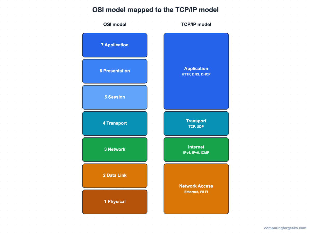
OSI layers 5, 6 and 7 collapse into one Application layer in the TCP/IP model, and layers 1 and 2 collapse into one Network Access layer. That single mapping answers most of what people search about the OSI model, and the rest follows from how each layer wraps the data it hands down. You will still hear layers called by their OSI number (“a Layer 2 problem”) even though the protocols on the wire are TCP/IP, so you need both models and the line between them.
We give the direct answers first: the layer mapping, the TCP/IP order from top to bottom, and the one layer that adds a trailer. After that come all seven OSI layers with their PDUs, where TLS, QUIC and ARP really sit, and the encapsulation of one HTTP request. Every layer is then confirmed in a real capture (tshark 4.6 on Ubuntu 26.04, re-run in October 2026), down to the byte count of each header you will see on your own machine.
Map the OSI model to the TCP/IP model
The TCP/IP model has fewer layers because it merges the ones that real software never separated. The original four-layer model in RFC 1122 names them Application, Transport, Internet and Link, and many textbooks and Cisco Networking Academy call the bottom one Network Access. Cisco’s CCNA material also uses a five-layer variant that keeps Physical and Data Link apart, because switching lives at Layer 2 and cabling faults live at Layer 1, and you troubleshoot them differently.
| OSI layer | TCP/IP 4-layer (RFC 1122) | TCP/IP 5-layer (Cisco) | Example protocols |
|---|---|---|---|
| 7 Application, 6 Presentation, 5 Session | Application | Application | HTTP, DNS, SMTP, SSH, TLS |
| 4 Transport | Transport | Transport | TCP, UDP |
| 3 Network | Internet | Network | IPv4, IPv6, ICMP |
| 2 Data Link | Link (Network Access) | Data Link | Ethernet, Wi-Fi, 802.1Q |
| 1 Physical | Link (Network Access) | Physical | Copper, fibre, radio |
Read the table from the middle out. Transport and Network line up one to one in both models. So “Layer 3” and “Layer 4” mean the same thing whichever model someone learned. All the merging happens at the edges: three OSI layers fold into the top, two fold into the bottom. The side-by-side view makes that overlap obvious:
Four questions come up constantly in interviews, on networking quiz sites and in the Cisco CCNA 200-301 exam, so each one gets its answer in the first sentence.
Which three layers of the OSI model map to the TCP/IP application layer?
Session (5), Presentation (6) and Application (7), three layers of the OSI model, map to the single Application layer of the TCP/IP model. TCP/IP merges them because applications do that work themselves. A browser handles its own sessions, character encoding and compression, and TLS encryption usually runs as a library inside the application process, so nothing in the operating system’s network stack sits at a separate Layer 5 or 6.
Which two OSI layers map to the TCP/IP network access layer?
Physical (1) and Data Link (2), the bottom two layers of the OSI model, map to the single Network Access layer of the four-layer TCP/IP model, which RFC 1122 calls the Link layer. One standard covers both in practice. IEEE 802.3 Ethernet defines the cable signalling and the frame format together, and the NIC implements both in the same chip, so TCP/IP treats them as one layer that “gets a frame onto the local link”.
What is the order of the TCP/IP layers from top to bottom?
From the top layer to the bottom, the four TCP/IP layers run in this order:
- Application
- Transport
- Internet
- Network Access (Link)
Cisco’s five-layer version reads Application, Transport, Network, Data Link, Physical. When you see “Internet” as a layer name, the question uses the four-layer model. When you see “Data Link” and “Physical” listed separately, it uses the five-layer one.
Which is the only OSI layer to add a trailer during encapsulation?
Only the Data Link layer (Layer 2) adds a trailer as well as a header. On Ethernet that trailer is the 4-byte Frame Check Sequence (FCS), a CRC computed over the whole frame so the receiving NIC can drop a frame that was corrupted on the wire. Every other layer only prepends a header, which is why the capture further down shows an Ethernet header but no trailer at all.
Learn the seven OSI model layers
Each OSI layer has a number, a name, a name for its data unit (the PDU), and a set of protocols and devices that work there. Layers 2, 3 and 4 come up constantly in commands, error messages and firewall rules, so their numbers and PDU names are worth knowing without stopping to think.
| Layer | Name | PDU | Job | Protocols and devices |
|---|---|---|---|---|
| 7 | Application | data | Interface to network applications | HTTP, DNS, SMTP, SSH |
| 6 | Presentation | data | Encoding, compression, encryption | TLS (conceptually), JPEG, UTF-8 |
| 5 | Session | data | Opens and closes sessions between hosts | RPC, NetBIOS session service |
| 4 | Transport | segment (TCP), datagram (UDP) | End-to-end delivery, ports, flow control | TCP, UDP; firewalls filter here |
| 3 | Network | packet | Logical addressing and routing | IPv4, IPv6, ICMP; routers |
| 2 | Data Link | frame | MAC addressing, delivery on one link | Ethernet, Wi-Fi, 802.1Q; switches |
| 1 | Physical | bits | Signals on the medium | Cables, transceivers; hubs, repeaters |
To remember the order, the usual mnemonics are “Please Do Not Throw Sausage Pizza Away” from Layer 1 up and “All People Seem To Need Data Processing” from Layer 7 down. Layers 5 and 6 rarely matter on their own, so treat them as part of the application story. The Data Link layer carries more detail than its one table row suggests: it splits into the LLC sublayer, which talks to the layer above, and the MAC sublayer, which handles media access and the hardware address burned into the NIC.
Layer numbers double as a troubleshooting map, and that is the main reason we still teach OSI numbering to every new engineer. A hub repeats signals at Layer 1, a switch forwards frames by MAC address at Layer 2, and a router forwards packets by IP address at Layer 3. So when someone calls a fault “Layer 1” you check cabling and link lights, “Layer 2” points at MAC tables and VLANs, and “Layer 3” points at addressing and routes. Naming the layer narrows the fix before you’ve typed a single command, and the guide to routers, switches and firewalls covers each device in more depth.
Place modern protocols on the stack
OSI dates from 1984, and some protocols do not fit neatly into one row. When a textbook and a forum post disagree on where a protocol lives, check which header carries it. That rule settles most arguments:
| Protocol | Carried inside | Usual layer | Why it’s ambiguous |
|---|---|---|---|
| TLS | TCP | 6 (conceptually), TCP/IP Application | Encrypts application data but runs as a library inside the app |
| QUIC / HTTP/3 | UDP | 4 and 7 together | Rebuilds reliability and congestion control on top of UDP and bakes in TLS 1.3 |
| ARP | Ethernet frame, EtherType 0x0806 | 2 (often called “2.5”) | Resolves Layer 3 addresses but never touches an IP header |
| ICMP | IPv4, protocol 1 | 3 | Rides inside IP yet exists only to serve IP |
| IPv6 Neighbor Discovery | ICMPv6 | 3 | Does ARP’s job (finding a neighbour’s MAC) using a Layer 3 protocol |
| 802.1Q VLAN tag | Ethernet header (+4 bytes) | 2 | Adds a field inside the existing header rather than a new layer |
Most guides still get QUIC wrong. Defined in RFC 9000, it runs over UDP, yet it does the job TCP used to do (ordered delivery, retransmission, congestion control), so a firewall that only sees “UDP 443” is blind to a full transport protocol. So HTTP/3 traffic looks like UDP in a capture even though it behaves like TCP plus TLS. The TCP vs UDP comparison covers the two classic transports side by side.
Follow encapsulation down the stack
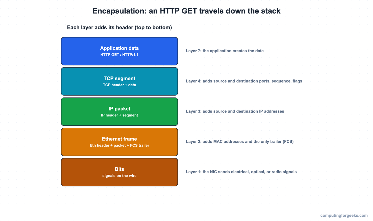
Encapsulation is each layer wrapping the data from the layer above in its own header before passing it down. A browser sending an HTTP GET to a web server makes it concrete, in five steps from top to bottom:
- Layer 7 creates the application data: the HTTP GET request.
- Layer 4 adds a TCP header with source and destination ports, a sequence number and flags. The unit is now a segment.
- Layer 3 adds an IP header with source and destination IP addresses. The unit is now a packet.
- Layer 2 adds an Ethernet header (destination MAC, source MAC, EtherType) and the FCS trailer. The unit is now a frame.
- Layer 1 turns the frame into electrical, optical or radio signals: bits on the medium.
Each step keeps everything from the steps above intact and prepends its own header, and only Layer 2 appends anything. The PDU names (segment, packet, frame, bits) follow directly from the layer that creates them:
One detail decides a lot of routing questions. The IP packet is end to end, but the frame is hop to hop. At each router the frame is stripped, the IP header is read for the routing decision, and a brand new frame is built for the next link with new source and destination MAC addresses. The Layer 3 packet survives the whole journey while the Layer 2 frame is rebuilt at every hop, which is how a router forwards a packet and why the capture below shows your gateway’s MAC address as the destination, not the web server’s.
Understand de-encapsulation and peer layers
De-encapsulation is the same process in reverse, bottom to top. The receiving NIC turns the bits back into a frame, checks the FCS and drops the frame if it fails, then strips the Ethernet header and hands the packet up. Layer 3 confirms the destination IP belongs to this host and passes the segment up. Layer 4 then reorders and acknowledges as needed before delivering the data to the application on the right port.
Two interaction terms describe what is going on, and you will see them mixed up often. Adjacent-layer interaction is one layer serving the layer directly above it on the same host, as when TCP asks IP on the same machine to deliver its segment. Same-layer interaction is the same layer on two different hosts talking through the header fields they exchange. For example, TCP on host A sets a sequence number that TCP on host B reads and acknowledges. The header is the conversation between peers; the handoff inside the stack is the conversation between neighbours.
Capture the OSI layers with tshark
The fastest way to make the model stop being abstract is to capture one request and expand it. You need tshark (the command-line Wireshark) and a plain HTTP site, because HTTPS hides the application headers inside TLS. On Ubuntu, preseed the “allow non-root capture” answer so you do not have to run the capture as root, then install the tools:
echo "wireshark-common wireshark-common/install-setuid boolean true" | sudo debconf-set-selections
sudo apt update
sudo DEBIAN_FRONTEND=noninteractive apt install -y tshark curl dnsutils
Add your user to the wireshark group, then log out and back in so the new group applies:
sudo usermod -aG wireshark $USERAfter logging back in, confirm the version:
tshark --version | head -1Our Ubuntu 26.04 VM pulled the 4.6 branch, and you should see a 4.6.x release on yours:
TShark (Wireshark) 4.6.4.Find the interface name before capturing, since it is eth0 on some VMs and ens18 or enp1s0 on others. The same command also shows your Layer 2 address:
ip -br linkThe lab VM has one interface, eth0, with MAC bc:24:11:81:27:1b:
lo               UNKNOWN        00:00:00:00:00:00 <LOOPBACK,UP,LOWER_UP>
eth0             UP             bc:24:11:81:27:1b <BROADCAST,MULTICAST,UP,LOWER_UP>
Start the capture in one terminal. We ran it as a normal user in the wireshark group, so no sudo is needed. Write the file to /tmp, not your home directory, because the Ubuntu 26.04 AppArmor profile for tshark refuses to read capture files from $HOME (the error and fix are at the end of this section):
tshark -i eth0 -f "tcp port 80" -w /tmp/capture.pcapFrom a second terminal, send one plain HTTP request. We first tried neverssl.com, the usual choice for this, but its SYNs kept going unanswered from the lab, so example.com is used here because it still answers on port 80:
curl -s -o /dev/null -w "%{http_code}\n" http://example.com/A 200 means the request completed. Stop the capture with Ctrl+C, and tshark reports what it saved:
Capturing on 'eth0'
12 packets captured
Twelve packets cover the whole conversation: the handshake, the GET, the response, the ACKs and the three FIN and ACK packets that close the connection. Only one of them, the GET, is needed to see every layer.
Read the layer stack in one frame
The -V flag prints the full protocol tree, which runs past 100 lines for a single GET. Every layer starts with an unindented line. Filtering for lines that begin with a capital letter leaves exactly one line per layer:
tshark -r /tmp/capture.pcap -Y http.request -V | grep -E '^[A-Z]'You are looking at the encapsulation list from earlier, read off a real frame from the top down:
Frame 4: Packet, 141 bytes on wire (1128 bits), 141 bytes captured (1128 bits) on interface eth0, id 0
Ethernet II, Src: ProxmoxServe_81:27:1b (bc:24:11:81:27:1b), Dst: eacAUTOMATIO_2b:cd:43 (00:e0:67:2b:cd:43)
Internet Protocol Version 4, Src: 192.168.1.50, Dst: 172.66.147.243
Transmission Control Protocol, Src Port: 60078, Dst Port: 80, Seq: 1, Ack: 1, Len: 75
Hypertext Transfer Protocol
Wireshark’s “Frame” line is its own metadata about the capture (length, interface, arrival time), not an OSI layer. Below it sit Ethernet II (Layer 2), IPv4 (Layer 3), TCP (Layer 4) and HTTP (Layer 7), in exactly the order encapsulation built them. You will find no Layer 5 or 6 line, which is the TCP/IP model showing through, because nothing on the wire carries a session or presentation header.
Look at the destination MAC. It is not example.com’s, because example.com is on another network. In our capture it belongs to the default gateway, and the neighbour table proves it:
ip neigh showThe gateway at 192.168.1.1 owns 00:e0:67:2b:cd:43, the same address in the Ethernet header:
192.168.1.1 dev eth0 lladdr 00:e0:67:2b:cd:43 REACHABLE You are seeing the hop-to-hop frame in action. The IP header names the final destination, while the Ethernet header only names the next device on the local link. ARP resolved that entry earlier, and the kernel keeps it cached, so no ARP exchange had to happen before the SYN.
Measure each header in bytes
tshark can print individual header fields, which turns encapsulation into arithmetic you can check:
tshark -r /tmp/capture.pcap -Y http.request -T fields -E header=y -e frame.len -e eth.type -e ip.hdr_len -e ip.len -e tcp.hdr_len -e tcp.lenYou get one tab-separated row back:
frame.len	eth.type	ip.hdr_len	ip.len	tcp.hdr_len	tcp.len
141	0x0800	20	127	32	75
Start from the 75 bytes of HTTP request, which sit inside a 32-byte TCP header, which makes a 107-byte segment. Add the 20-byte IPv4 header and you get the 127-byte packet that ip.len reports. Add the 14-byte Ethernet header (6 bytes destination MAC, 6 bytes source MAC, 2 bytes EtherType 0x0800 for IPv4) and you land on the 141-byte frame. The TCP header is 32 bytes rather than the 20-byte minimum because the two hosts negotiated TCP timestamps, which add 12 bytes of options (two NOPs plus the 10-byte timestamp field) to each segment, so headers alone cost 66 bytes here, almost as much as the request they carry.
Notice what the sum leaves out: the 4-byte FCS trailer. Linux captures an outbound frame before the NIC appends the FCS, and on receive the NIC checks the FCS and strips it before the kernel sees the frame, so asking for the field with -e eth.fcs on this capture prints an empty line either way. The trailer is still on the wire; Wireshark only shows it on hardware that passes it through.
Our lab box rendered the same summary like this:

Every number in that screenshot came off one 141-byte frame. Repeat the sum on your own capture and you will land on your own frame length.
Watch same-layer interaction in the handshake
Reading the first four packets shows the TCP three-way handshake that comes before any HTTP data. This is same-layer interaction on display: the SYN carries Seq=0, the SYN-ACK answers with Ack=1, and the ACK confirms before the GET leaves in packet 4. TCP on each host is talking to TCP on the other purely through flags and numbers in the Layer 4 header:
tshark -r /tmp/capture.pcap -c 4Both SYN packets also carry each side’s MSS, the largest segment it will accept (1460 from the client, 1400 from the server), and each sender keeps its segments under the other side’s figure:

No HTTP byte moves until packet 3 completes the handshake, which is why a firewall that drops SYN-ACKs breaks every new TCP connection while UDP traffic keeps flowing.
Compare a UDP request at Layer 4
Swap HTTP for DNS and only one layer changes. Try it. Capture UDP port 53 the same way (tshark -i eth0 -f "udp port 53" -w /tmp/dns.pcap), send a query straight to a public resolver so the local cache can’t answer it, then expand the query packet:
dig @1.1.1.1 example.com A +shortOnce the answer prints, stop the capture and read the query frame:
tshark -r /tmp/dns.pcap -Y 'dns.flags.response == 0' -V | grep -E '^[A-Z]'Ethernet and IPv4 look exactly as before; Layer 4 is now User Datagram Protocol and Layer 7 is DNS:
Frame 1: Packet, 94 bytes on wire (752 bits), 94 bytes captured (752 bits) on interface eth0, id 0
Ethernet II, Src: ProxmoxServe_81:27:1b (bc:24:11:81:27:1b), Dst: eacAUTOMATIO_2b:cd:43 (00:e0:67:2b:cd:43)
Internet Protocol Version 4, Src: 192.168.1.50, Dst: 1.1.1.1
User Datagram Protocol, Src Port: 46371, Dst Port: 53
Domain Name System (query)
UDP’s header is a fixed 8 bytes with no handshake, sequence numbers or options, which is why the whole query fits in a 94-byte frame and needs no setup packets first. That is the Layer 4 trade in one line. TCP spends three setup packets and a 20 to 60 byte header (32 here) on reliability, while UDP spends 8 bytes and leaves retries to the application. The same IPv4 addressing sits underneath both.
Error: “tshark: You don’t have permission to read the file”
On Ubuntu 26.04, writing the capture to your home directory works, but reading it back fails even though you own the file:
tshark: You don't have permission to read the file "/home/josphat/capture.pcap".File permissions are not the cause. The apparmor package ships a tshark profile that lets the dumpcap helper write *.pcap files anywhere but only lets tshark itself read from temporary directories, and the kernel log shows the denial:
sudo dmesg | grep 'profile="tshark"'Look for apparmor="DENIED" with your capture path in name=:
audit: type=1400 audit(1792990245.351:409): apparmor="DENIED" operation="open" class="file" profile="tshark" name="/home/josphat/capture.pcap" pid=29275 comm="tshark" requested_mask="r" denied_mask="r" fsuid=1000 ouid=1000We keep capture files in /tmp for exactly this reason, and it is the simplest fix. If you’d rather read captures from your home directory, add a rule to the profile’s local override file, which survives package upgrades, and reload the profile:
echo 'owner @{HOME}/** r,' | sudo tee -a /etc/apparmor.d/local/tshark
sudo apparmor_parser -r /etc/apparmor.d/tshark
After the reload, tshark -r ~/capture.pcap reads the file without the error. The owner keyword limits the rule to files you own, so tshark still can’t read other users’ captures.
Practice the OSI and TCP/IP models
Drill the layer numbers, PDU names and the OSI to TCP/IP mapping with the flashcards, then test yourself on the quiz. The deck is also a downloadable Anki package for spaced repetition.
Now check yourself on the mapping, encapsulation order and the interaction terms:
If you’re working toward the Cisco CCNA 200-301, the textbook treatment of this topic is the opening chapter of Wendell Odom’s CCNA 200-301 Official Cert Guide Library (paid link), which uses the five-layer TCP/IP view shown in the mapping table above. The CCNA book comparison covers which edition to buy and when the alternatives make more sense.
Common OSI model misconceptions
Most wrong answers about the OSI model come from a handful of beliefs that sound right. You can disprove each one below with the capture above:
- “The Internet runs on OSI.” It runs on TCP/IP. OSI is the numbering everyone uses to talk about it, and no packet carries a Layer 5 or 6 header.
- “Every layer adds a header and a trailer.” Only Layer 2 adds a trailer, and a normal capture never shows it because the NIC adds it after capture on transmit and strips it on receive.
- “The destination MAC is the server’s MAC.” Only on the same subnet. Off the subnet it is the gateway’s, as
ip neighshowed. - “A switch is always Layer 2 and a router always Layer 3.” A multilayer switch routes between VLANs at Layer 3, and the job a device is doing decides its layer.
- “UDP traffic on port 443 is not encrypted web traffic.” It is very likely HTTP/3 over QUIC, with TLS 1.3 built in.
Get the layer numbers, PDU names and the 7-6-5 and 2-1 merges solid, and the rest of networking reads as variations on where a protocol sits and which header it adds. From here, the IP routing primer picks up the Layer 3 story, and the CCNA 200-301 study roadmap shows where this foundation leads next.