Static routes work fine until you have more than a few of them. Single-area OSPF is where most networks reach for a dynamic routing protocol: the routers discover each other, exchange a map of the topology, and keep their routing tables in sync on their own, with no more static routes to maintain. The whole thing takes only a handful of commands per router.
This guide configures single-area OSPFv2 on three Cisco routers two different ways (the network-statement method and the newer interface method), makes the LAN interfaces passive, advertises a default route into the area, then verifies everything with the show commands that prove it converged. After that we break the adjacency five common ways and show the exact log line each fault leaves behind. It’s the hands-on counterpart to the OSPF concepts guide, so start there if neighbors, DR/BDR and cost are still new.
Built on three Cisco IOS 15.2 routers in GNS3, with every fault in the troubleshooting section reproduced on the same lab in October 2026.
The lab topology
Three routers sit in a line, all in OSPF area 0. R1 is the edge router with a path to the internet, R2 is the transit router in the middle, and R3 is a branch. Each router has a LAN, and R1 hands a default route to the rest of the area so R2 and R3 know how to reach the outside world.

The addressing is deliberately simple so the routes are easy to read later. Every link is a /30, every LAN is a /24, and the router IDs are clean numbers:
| Device | Interface | Address | Purpose |
|---|---|---|---|
| R1 | Gi0/0 | 10.0.12.1/30 | Link to R2 |
| R1 | Loopback1 | 10.1.1.1/24 | LAN (passive) |
| R2 | Gi0/0 | 10.0.12.2/30 | Link to R1 |
| R2 | Gi1/0 | 10.0.23.2/30 | Link to R3 |
| R2 | Loopback1 | 10.2.2.2/24 | LAN (passive) |
| R3 | Gi0/0 | 10.0.23.1/30 | Link to R2 |
| R3 | Loopback1 | 10.3.3.3/24 | LAN (passive) |
In the lab each LAN is a loopback, with ip ospf network point-to-point set so it advertises the whole /24 instead of a /32 host route. On real hardware that LAN is the physical interface facing your switch, which advertises as a /24 with no extra step, and every command below is identical. The complete R1, R2, and R3 configurations are in the companion lab repo if you want to load them directly. This is the same lab as it ran in GNS3 on c7200 routers:
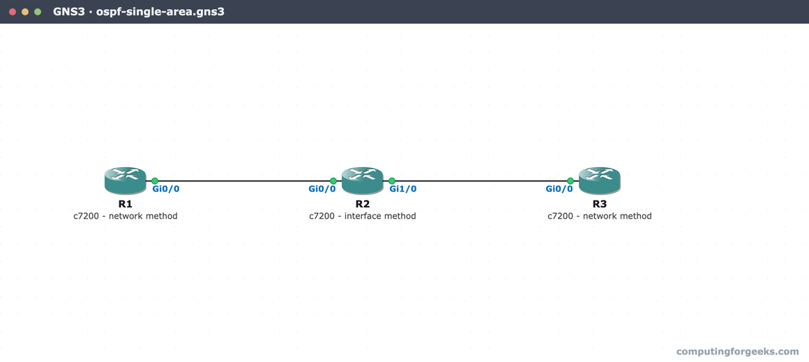
Assume the interfaces are already addressed as shown in the table. Everything from here is OSPF configuration, starting on R1.
Step 1: Enable OSPF and set the router ID
Start the OSPF process and pin the router ID by hand. On R1:
configure terminal
router ospf 1
 router-id 1.1.1.1
The 1 after router ospf is a process ID. It is locally significant, so R1 can run process 1 while another router runs process 50 and they still form an adjacency. R2 and R3 get the same two lines with their own IDs, 2.2.2.2 and 3.3.3.3.
Always set the router ID explicitly. Left to itself OSPF picks the highest loopback IP, or failing that the highest active interface IP, and a clean manual ID makes every later show command readable. One catch: the router ID is chosen once, when the process starts. If you change it on a process that already has neighbors, the new ID does not take effect until you restart the process:
clear ip ospf processThat command prompts with Reset ALL OSPF processes? [no]:, so type yes to confirm. It drops and rebuilds every adjacency, so use it deliberately on a live network.
Step 2: Advertise the interfaces, two ways
An interface only runs OSPF once you tell the process about it. There are two ways to do that, and this lab uses both so you can see them side by side.
The network-statement method (R1 and R3)
Under the OSPF process, a network statement matches interfaces by address and drops them into an area. On R1:
router ospf 1
 network 10.0.12.0 0.0.0.3 area 0
 network 10.1.1.0 0.0.0.255 area 0
The trailing value on each line is a wildcard mask, not a subnet mask. It is the inverse: a /30 (255.255.255.252) becomes 0.0.0.3, and a /24 becomes 0.0.0.255. The statement matches any interface whose address falls in that range and activates OSPF on it. R3 is configured the same way for its own subnets:
router ospf 1
 network 10.0.23.0 0.0.0.3 area 0
 network 10.3.3.0 0.0.0.255 area 0
That handles the two routers using network statements. R2, sitting between them, is configured a different way.
The interface method (R2)
The cleaner alternative skips network statements entirely. You enable OSPF directly on each interface, which is far easier to read on a router with many interfaces. R2 uses this method:
interface GigabitEthernet0/0
 ip ospf 1 area 0
interface GigabitEthernet1/0
 ip ospf 1 area 0
interface Loopback1
 ip ospf 1 area 0
The ip ospf 1 area 0 command creates process 1 if it does not exist, so on R2 you only drop back to router ospf 1 to set the router ID. Both methods produce identical adjacencies and routes; pick one per router and stay consistent.
Step 3: Make the LAN interfaces passive
A LAN holds end hosts, not routers, so there is no reason to send OSPF Hellos out of it. Sending them anyway wastes effort and exposes the protocol to anyone who plugs in. Mark the LAN passive:
router ospf 1
 passive-interface Loopback1
Passive does not remove the network from OSPF. The subnet is still advertised to the rest of the area; the router just stops forming adjacencies out that interface. On a router with many user-facing interfaces, the usual pattern is to flip the default and re-enable only the links you want:
router ospf 1
 passive-interface default
 no passive-interface GigabitEthernet0/0
With the links adjacency-ready and the LANs quiet, one piece is missing: the branch routers still have no way out to the internet.
Step 4: Advertise a default route into OSPF
R2 and R3 have no idea how to reach the internet. Rather than configure a static default on each of them, let R1 inject one route that every router in the area inherits. R1 first needs a default route of its own (here a placeholder pointing at Null0 stands in for the real internet next hop), then it originates it:
ip route 0.0.0.0 0.0.0.0 Null0
router ospf 1
 default-information originate
The default-information originate command only injects a default if one already exists in the routing table, unless you append always. With its own default route in place, R1 becomes an autonomous system boundary router, and the default appears on every other router as an external OSPF route. This is the dynamic-routing version of what you would otherwise hand-craft with static routes on each device.
Step 5: Verify the adjacencies
Configuration done. The first thing to confirm is that the routers actually became neighbors. On R2, which sits between the other two, show ip ospf neighbor should list both, and show ip ospf interface brief gives a one-line summary of every OSPF-enabled interface:
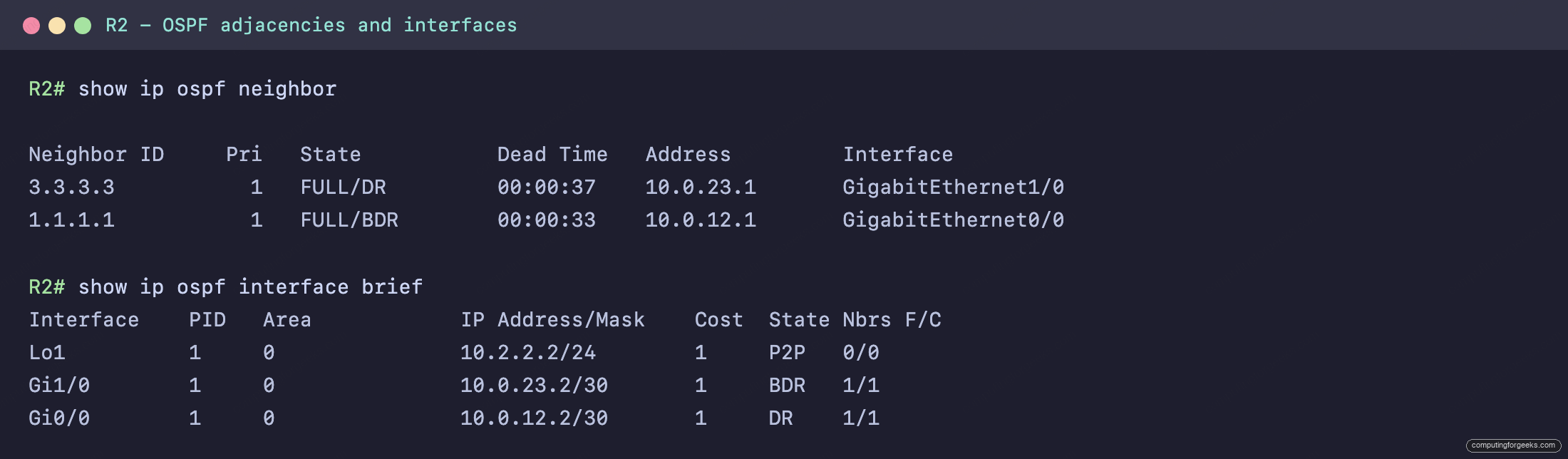
The same capture as text, so you can line it up against your own routers:
R2# show ip ospf neighbor

Neighbor ID     Pri   State           Dead Time   Address         Interface
3.3.3.3           1   FULL/DR         00:00:37    10.0.23.1       GigabitEthernet1/0
1.1.1.1           1   FULL/BDR        00:00:33    10.0.12.1       GigabitEthernet0/0

R2# show ip ospf interface brief
Interface    PID   Area            IP Address/Mask    Cost  State Nbrs F/C
Lo1          1     0               10.2.2.2/24        1     P2P   0/0
Gi1/0        1     0               10.0.23.2/30       1     BDR   1/1
Gi0/0        1     0               10.0.12.2/30       1     DR    1/1
Both neighbors show FULL, which means their link-state databases are synchronized. The role after the slash is the result of the DR/BDR election that runs on every Ethernet segment, even a two-router /30 link: R2 is the DR toward R1 and the BDR toward R3. The interface brief confirms the interface method worked, listing Gi0/0, Gi1/0, and Lo1 all in area 0, each with a cost of 1.
To check the other side, show ip protocols on R1 summarizes how the process is actually configured. It is the fastest way to confirm the network statements, the passive interface, and the default-route origination all landed:
R1# show ip protocols
*** IP Routing is NSF aware ***

Routing Protocol is "ospf 1"
  Outgoing update filter list for all interfaces is not set
  Incoming update filter list for all interfaces is not set
  Router ID 1.1.1.1
  It is an autonomous system boundary router
 Redistributing External Routes from,
  Number of areas in this router is 1. 1 normal 0 stub 0 nssa
  Maximum path: 4
  Routing for Networks:
    10.0.12.0 0.0.0.3 area 0
    10.1.1.0 0.0.0.255 area 0
  Passive Interface(s):
    Loopback1
  Routing Information Sources:
    Gateway         Distance      Last Update
    3.3.3.3              110      00:00:21
    2.2.2.2              110      00:00:31
  Distance: (default is 110)
Router ID 1.1.1.1, the two advertised networks, Loopback1 listed as passive, and the line “It is an autonomous system boundary router” confirming the default origination, all in one screen.
Step 6: Verify the routes
Adjacencies up is not the goal; routes in the table is. On R3, at the far end of the lab, show ip route ospf should hold every subnet it did not configure itself, plus the default that R1 originated. The ping proves the data path actually works end to end:
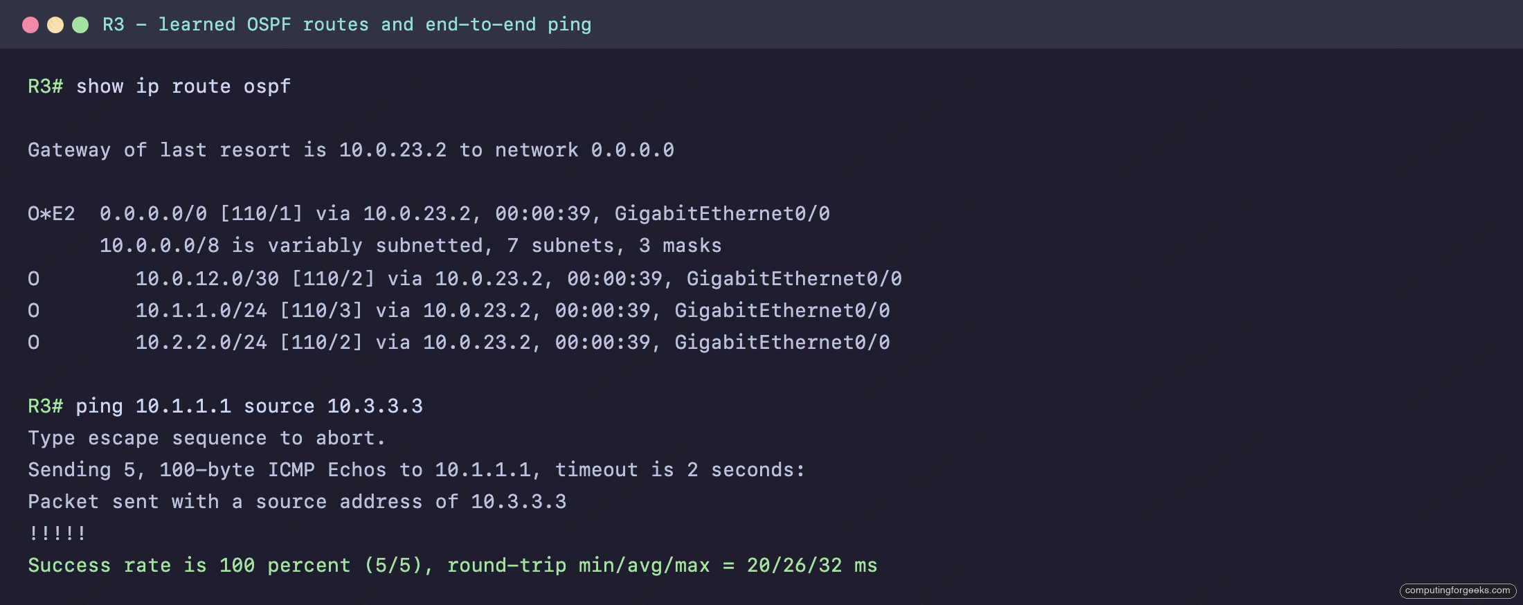
Here are both commands as text, with the route code legend trimmed from the first one:
R3# show ip route ospf

Gateway of last resort is 10.0.23.2 to network 0.0.0.0

O*E2  0.0.0.0/0 [110/1] via 10.0.23.2, 00:00:39, GigabitEthernet0/0
      10.0.0.0/8 is variably subnetted, 7 subnets, 3 masks
O        10.0.12.0/30 [110/2] via 10.0.23.2, 00:00:39, GigabitEthernet0/0
O        10.1.1.0/24 [110/3] via 10.0.23.2, 00:00:39, GigabitEthernet0/0
O        10.2.2.0/24 [110/2] via 10.0.23.2, 00:00:39, GigabitEthernet0/0

R3# ping 10.1.1.1 source 10.3.3.3
Type escape sequence to abort.
Sending 5, 100-byte ICMP Echos to 10.1.1.1, timeout is 2 seconds:
Packet sent with a source address of 10.3.3.3
!!!!!
Success rate is 100 percent (5/5), round-trip min/avg/max = 20/26/32 ms
Read the codes left to right. O is an OSPF route, O*E2 is the external default that R1 injected, and the bracketed pair is the administrative distance and cost. R3 learned R1’s LAN as O 10.1.1.0/24 [110/3]: distance 110, cost 3. OSPF cost is the sum of the outgoing interface costs along the path, counted all the way to the interface that holds the destination network: R3’s Gi0/0 toward R2 (1), R2’s Gi0/0 toward R1 (1), and R1’s Loopback1, where 10.1.1.0/24 lives (1). That is two links but three interface costs, which is why cost is not a hop count; R2’s LAN, one link away, shows as cost 2, and the default stays at [110/1] however far away it is, because an E2 route keeps the cost R1 assigned to it (the calculation is defined in RFC 2328, section 16.1, with the external E2 cost in section 16.4). The ping from R3’s LAN to R1’s LAN succeeds at 100 percent, which means the routes on every router in between agree.
R1 sees the mirror image. Its show ip route ospf learns R3’s LAN at the same cost of 3 from the opposite direction (the route code legend and the Gateway of last resort is 0.0.0.0 to network 0.0.0.0 line are trimmed here):
R1# show ip route ospf
      10.0.0.0/8 is variably subnetted, 7 subnets, 3 masks
O        10.0.23.0/30 [110/2] via 10.0.12.2, 00:00:22, GigabitEthernet0/0
O        10.2.2.0/24 [110/2] via 10.0.12.2, 00:00:32, GigabitEthernet0/0
O        10.3.3.0/24 [110/3] via 10.0.12.2, 00:00:22, GigabitEthernet0/0
For a deeper walk through every code and column in this output, see the guide on reading the routing table.
Step 7: Tune the OSPF cost
Look back at the interface brief: every link shows a cost of 1. That is because OSPF cost is the reference bandwidth (100 Mbps by default) divided by the interface bandwidth, with a floor of 1, so FastEthernet, Gigabit and faster links all collapse to the same value. On a modern network that hides real differences between a 1G and a 10G link.
The fix is to raise the reference bandwidth, and the rule is to set the same value on every router so the math stays consistent:
router ospf 1
 auto-cost reference-bandwidth 10000
When you need to steer traffic onto or off a specific link regardless of bandwidth, set the cost directly on the interface instead:
interface GigabitEthernet0/0
 ip ospf cost 50
A direct interface cost always overrides the bandwidth-derived value, which makes it the cleanest tool for path selection when you have two ways to reach the same place.
Troubleshoot OSPF neighbors that won’t form
Most OSPF problems come down to two routers that refuse to become neighbors, and the cause is rarely visible in show ip ospf neighbor, which simply shows nothing. To see what each common cause looks like, we cut the lab down to R1 and R2 on the 10.0.12.0/30 link, turned on buffered logging with millisecond timestamps (logging buffered 64000 debugging, service timestamps log datetime msec and service timestamps debug datetime msec) plus no logging console so debug output lands in the buffer instead of flooding the console, and broke the adjacency five ways. The habit worth taking from this section is to read show logging | include OSPF on both routers, because the router that detects a fault is often not the one you’re logged into.
%OSPF-4-ERRRCV: Received invalid packet: mismatched area ID
We moved R2’s Gi0/0 into area 1 with ip ospf 1 area 1 while R1 stayed in area 0. Only R2 logged the reason. Both routers drop the other’s Hellos, but only the router whose interface sits outside area 0 logs ERRRCV: an area 0 Hello arriving on a non-backbone interface fails the virtual-link check that the log line names. R2 repeated the error roughly every nine seconds. The first line is the old area 0 adjacency going down as the interface left the area (the first three of seven lines shown):
R2# show logging | include OSPF
*Oct 14 09:40:29.095: %OSPF-5-ADJCHG: Process 1, Nbr 1.1.1.1 on GigabitEthernet0/0 from FULL to DOWN, Neighbor Down: Interface down or detached
*Oct 14 09:40:37.671: %OSPF-4-ERRRCV: Received invalid packet: mismatched area ID, from backbone area must be virtual-link but not found from 10.0.12.1, GigabitEthernet0/0
*Oct 14 09:40:46.959: %OSPF-4-ERRRCV: Received invalid packet: mismatched area ID, from backbone area must be virtual-link but not found from 10.0.12.1, GigabitEthernet0/0
R1, still in area 0, never logged an ERRRCV line. All it recorded was the neighbor dying on the dead timer, so if you only look at R1 you see the symptom and not the cause:
R1# show logging | include OSPF
*Oct 14 09:41:03.363: %OSPF-5-ADJCHG: Process 1, Nbr 2.2.2.2 on GigabitEthernet0/0 from FULL to DOWN, Neighbor Down: Dead timer expired
The Area column in R2’s interface brief gives it away on the misconfigured side, showing area 1 and no neighbors:
R2# show ip ospf interface brief
Interface    PID   Area            IP Address/Mask    Cost  State Nbrs F/C
Gi0/0        1     1               10.0.12.2/30       1     DR    0/0
Put both ends of the link in the same area (ip ospf 1 area 0 on R2 here) and the adjacency comes back on the next Hello.
Mismatched hello parameters from 10.0.12.2
Hello and dead timers have to match on both ends of a link. We set ip ospf hello-interval 5 on R2 only, and IOS quietly changed R2’s dead interval to 20 seconds, four times the new Hello, which you can see by filtering the interface output for its timer line:
R1# show ip ospf interface GigabitEthernet0/0 | include Timer
  Timer intervals configured, Hello 10, Dead 40, Wait 40, Retransmit 5

R2# show ip ospf interface GigabitEthernet0/0 | include Timer
  Timer intervals configured, Hello 5, Dead 20, Wait 20, Retransmit 5
Without debugging, the only syslog message either router writes is the eventual dead-timer drop, so the cause only shows up with debug ip ospf hello running. In the debug line, R is the value received from the neighbor and C is the value configured locally, so R1 is telling you R2 sent Hello 5 and Dead 20 where it expected 10 and 40 (an excerpt from R1’s log buffer):
R1# show logging | include OSPF
*Oct 14 09:42:33.695: OSPF-1 HELLO Gi0/0: Rcv hello from 2.2.2.2 area 0 10.0.12.2
*Oct 14 09:42:33.695: OSPF-1 HELLO Gi0/0: Mismatched hello parameters from 10.0.12.2
*Oct 14 09:42:33.695: OSPF-1 HELLO Gi0/0: Dead R 20 C 40, Hello R 5 C 10 Mask R 255.255.255.252 C 255.255.255.252
The neighbor dropped on R1’s dead timer about 30 seconds later and stayed down. Removing the override with no ip ospf hello-interval brought it back to FULL. Turn the debug off with undebug all when you’re done, because on a busy router Hello debugging floods the log.
Neighbor stuck in EXSTART or EXCHANGE (MTU mismatch)
This one surprised us. Setting ip mtu 1400 on R2’s Gi0/0 did not drop the existing adjacency at all; R2 still showed R1 as FULL. MTU is only compared in the Database Description packets exchanged while an adjacency forms, so the mismatch stays hidden until something forces the neighbors to start over:
R2# show ip ospf neighbor

Neighbor ID     Pri   State           Dead Time   Address         Interface
1.1.1.1           1   FULL/BDR        00:00:35    10.0.12.1       GigabitEthernet0/0
After clear ip ospf process on R2 the two routers stalled halfway, and they stayed that way for more than a minute. R1 sat in EXCHANGE and R2 in EXSTART:
R1# show ip ospf neighbor

Neighbor ID     Pri   State           Dead Time   Address         Interface
2.2.2.2           1   EXCHANGE/BDR    00:00:36    10.0.12.2       GigabitEthernet0/0

R2# show ip ospf neighbor

Neighbor ID     Pri   State           Dead Time   Address         Interface
1.1.1.1           1   EXSTART/DR      00:00:39    10.0.12.1       GigabitEthernet0/0
With debug ip ospf adj on, each side reports the difference from its own point of view. R1, with the larger MTU, accepts R2’s packets and moves on to EXCHANGE. R2 sees R1 advertise a 1500-byte MTU in its Database Description packets, more than its own 1400 bytes can take, so it rejects them and keeps retransmitting its own (excerpts from each router’s log buffer):
R1# show logging | include OSPF
*Oct 14 09:44:38.255: OSPF-1 ADJ   Gi0/0: Rcv DBD from 2.2.2.2 seq 0x1E4 opt 0x52 flag 0x7 len 32  mtu 1400 state EXSTART
*Oct 14 09:44:38.255: OSPF-1 ADJ   Gi0/0: Nbr 2.2.2.2 has smaller interface MTU

R2# show logging | include OSPF
*Oct 14 09:44:37.675: OSPF-1 ADJ   Gi0/0: Rcv DBD from 1.1.1.1 seq 0x1DBC opt 0x52 flag 0x7 len 32  mtu 1500 state EXSTART
*Oct 14 09:44:37.675: OSPF-1 ADJ   Gi0/0: Nbr 1.1.1.1 has larger interface MTU
After 25 retransmissions IOS gives up on the neighbor, about two minutes after the reset in our lab (an excerpt from R1’s log):
R1# show logging | include OSPF
*Oct 14 09:46:36.619: OSPF-1 ADJ   Gi0/0: Killing nbr 2.2.2.2 due to excessive (25) retransmissions
*Oct 14 09:46:36.619: OSPF-1 ADJ   Gi0/0: 2.2.2.2 address 10.0.12.2 is dead, state DOWN
*Oct 14 09:46:36.619: %OSPF-5-ADJCHG: Process 1, Nbr 2.2.2.2 on GigabitEthernet0/0 from EXCHANGE to DOWN, Neighbor Down: Too many retransmissions
The proper fix is to make the MTU match on both ends. If you can’t, ip ospf mtu-ignore on the router with the smaller MTU (R2 here) is enough. Each router ignores the other for 60 seconds after killing it: R1 killed R2 at 09:46:36 and its ignore timer expired at 09:47:36, R2 killed R1 about five seconds later, and the two were FULL again at 09:47:49. Expect about a minute before the fix takes effect. On this IOS release show ip ospf interface does not show the interface MTU (we checked that before adding mtu-ignore, so we can’t say whether it lists the ignore setting), so check the MTU on the interface itself:
R2# show ip interface GigabitEthernet0/0 | include MTU
  MTU is 1400 bytes

R1# show logging | include ADJCHG
*Oct 14 09:46:36.619: %OSPF-5-ADJCHG: Process 1, Nbr 2.2.2.2 on GigabitEthernet0/0 from EXCHANGE to DOWN, Neighbor Down: Too many retransmissions
*Oct 14 09:47:36.619: %OSPF-5-ADJCHG: Process 1, Nbr 2.2.2.2 on GigabitEthernet0/0 from DOWN to DOWN, Neighbor Down: Ignore timer expired
*Oct 14 09:47:49.231: %OSPF-5-ADJCHG: Process 1, Nbr 2.2.2.2 on GigabitEthernet0/0 from LOADING to FULL, Loading Done
The middle line is R1’s ignore timer running out, a minute after it killed the neighbor; the LOADING to FULL line 13 seconds later is the adjacency re-forming with mtu-ignore in place on R2.
%OSPF-4-DUP_RTRID_NBR: OSPF detected duplicate router-id
Two routers with the same router ID can’t form an adjacency. We gave R2 the router ID 1.1.1.1, which R1 already uses, and IOS warned straight away that the change would only apply after a reload or a process reset:
R2(config-router)# router-id 1.1.1.1
% OSPF: Reload or use "clear ip ospf process" command, for this to take effect
After clear ip ospf process on R2, both routers logged the duplicate, the adjacency dropped, and it never came back:
R1# show logging | include OSPF
*Oct 14 09:49:38.879: %OSPF-4-DUP_RTRID_NBR: OSPF detected duplicate router-id 1.1.1.1 from 10.0.12.2 on interface GigabitEthernet0/0
*Oct 14 09:50:18.839: %OSPF-5-ADJCHG: Process 1, Nbr 2.2.2.2 on GigabitEthernet0/0 from FULL to DOWN, Neighbor Down: Dead timer expired

R2# show ip ospf | include ID
 Routing Process "ospf 1" with ID 1.1.1.1
This is the strongest argument for setting router-id by hand on every router. A duplicate usually comes from a copied configuration or a cloned lab template, and it clears with a unique ID plus another clear ip ospf process.
Passive interface on a transit link
A passive interface still advertises its subnet but sends no Hellos, which is right for a LAN and wrong for a link to another router. We made R1’s Gi0/0 passive, and R1 dropped the neighbor immediately while R2 only noticed when its dead timer ran out, 33 seconds later:
R1# show logging | include OSPF
*Oct 14 09:51:26.247: %OSPF-5-ADJCHG: Process 1, Nbr 2.2.2.2 on GigabitEthernet0/0 from FULL to DOWN, Neighbor Down: Interface down or detached

R2# show logging | include OSPF
*Oct 14 09:51:59.515: %OSPF-5-ADJCHG: Process 1, Nbr 1.1.1.1 on GigabitEthernet0/0 from FULL to DOWN, Neighbor Down: Dead timer expired
show ip protocols lists the link under Passive Interface(s), and show ip ospf interface (trimmed here to the three lines that matter) says it outright:
R1# show ip protocols
*** IP Routing is NSF aware ***

Routing Protocol is "ospf 1"
  Outgoing update filter list for all interfaces is not set
  Incoming update filter list for all interfaces is not set
  Router ID 1.1.1.1
  Number of areas in this router is 1. 1 normal 0 stub 0 nssa
  Maximum path: 4
  Routing for Networks:
    10.0.12.0 0.0.0.3 area 0
  Passive Interface(s):
    GigabitEthernet0/0
  Routing Information Sources:
    Gateway         Distance      Last Update
  Distance: (default is 110)

R1# show ip ospf interface GigabitEthernet0/0
  No backup designated router on this network
    No Hellos (Passive interface)
  Neighbor Count is 0, Adjacent neighbor count is 0
This mistake usually arrives with passive-interface default, when a new uplink is added and nobody adds the matching no passive-interface line. Removing the passive setting from the link brought the adjacency straight back to FULL.
Lab challenge: configure OSPF yourself
Practice this one without looking, because configuring OSPF on a router someone else has already addressed is the everyday version of the job (and how the Cisco CCNA 200-301 exam presents it in its simulation items). You are handed R3 with its interfaces addressed (Gi0/0 at 10.0.23.1/30 toward R2, Loopback1 at 10.3.3.3/24 as the LAN) but no routing protocol running. Your task:
- Start OSPF process 1 with router ID 3.3.3.3.
- Advertise both connected subnets into area 0 using network statements.
- Make the LAN interface passive.
- Confirm R3 reaches FULL with R2 and learns the default route.
Configure it, then check yourself against the solution.
Solution
The whole task is seven lines:
configure terminal
router ospf 1
 router-id 3.3.3.3
 network 10.0.23.0 0.0.0.3 area 0
 network 10.3.3.0 0.0.0.255 area 0
 passive-interface Loopback1
 end
Then verify the adjacency formed and the default arrived:
R3# show ip ospf neighbor

Neighbor ID     Pri   State           Dead Time   Address         Interface
2.2.2.2           1   FULL/BDR        00:00:31    10.0.23.2       GigabitEthernet0/0
If you see R2 as FULL and an O*E2 0.0.0.0/0 entry in show ip route ospf, you configured it correctly. If the neighbor never appears, the usual causes are a wildcard mask that does not match the interface, a missing no shutdown, or mismatched timers between the two ends.
Test yourself on OSPF configuration
Ten questions on the commands you just ran, from network statements and wildcard masks to passive interfaces and default-route origination. Each answer is checked against Cisco’s documentation or verified on the lab above.
Drill the commands until they are automatic with the flashcard deck. You can also download the same cards as an Anki deck and review them on your phone.
Your single-area OSPF verification checklist
OSPF is configured the same way every time, and it is verified the same way every time. When you finish a configuration, walk these four commands in order and you will catch almost any mistake before it bites:
- show ip ospf neighbor confirms the adjacencies reached FULL. Anything stuck below FULL is a neighbor problem, not a routing problem, and
show logging | include OSPFon both routers points to the cause, whiledebug ip ospf helloordebug ip ospf adjnames it when the log alone doesn’t. - show ip protocols confirms you advertised the right networks, made the right interfaces passive, and originated a default if you meant to.
- show ip ospf interface brief confirms which interfaces are in OSPF and at what cost, the fastest way to spot an interface you forgot or a cost you need to tune.
- show ip route ospf confirms the routes actually landed, with the expected
OandO*E2codes and a cost equal to the sum of the outgoing interface costs along the path (here 1 per interface, so R3 sees R1’s LAN at 3), with the E2 default at its originated cost of 1.
Single-area OSPF is the foundation the rest of the routing topics build on. Once this is second nature, the natural next steps are inter-VLAN routing and first-hop redundancy, which build on the same routed network. For the full path through the certification, follow the CCNA 200-301 study roadmap, and if you want the theory behind these commands, the routing protocols overview explains why link-state routing behaves the way it does.