

Hamming code is an error-correcting code used to detect and correct errors in data during transmission or storage. It adds extra bits called parity bits to the original data, allowing the system to identify and correct single-bit errors.
- It improves the accuracy and reliability of data transmission.
- It can detect and correct single-bit errors in the received data.
Redundant Bits
Redundant bits are extra bits added to the original data to help detect and correct errors during data transmission. In Hamming Code, these bits are placed at specific positions, which are the parity bits, to identify errors in the received data
The required number of redundant bits is determined using:
2r ≥ m + r + 1
where,
- m is the number of bits in the input data
- r is the number of redundant bits.
For example, if the data contains 7 bits, then:
= 24 ≥ 7 + 4 + 1
= 16 ≥ 12
Therefore, 4 redundant bits are required.
Types of Parity Bits
A parity bit is a bit added to a set of binary bits to ensure that the total number of 1's in the data is even or odd. Parity bits are used for error detection. There are two types of parity bits:
- Even Parity Bit: In the case of even parity, for a given set of bits, the number of 1’s are counted. If that count is odd, the parity bit value is set to 1, making the total count of occurrences of 1’s an even number. If the total number of 1’s in a given set of bits is already even, the parity bit's value is 0.
- Odd Parity Bit: In the case of odd parity, for a given set of bits, the number of 1’s are counted. If that count is even, the parity bit value is set to 1, making the total count of occurrences of 1’s an odd number. If the total number of 1’s in a given set of bits is already odd, the parity bit's value is 0.
Algorithm of Hamming Code
Hamming Code adds parity bits to the data bits so that errors can be detected and corrected during transmission. The parity bits are placed at positions that are powers of 2 and each parity bit checks a specific group of positions.
Step 1: Number the bit positions starting from 1 and write each position in binary form (1, 10, 11, 100, etc.).
Step 2: Mark the positions that are powers of 2 as parity-bit positions, such as 1, 2, 4, 8, etc.
Step 3: Fill all remaining positions with the data bits.
Step 4: Determine which positions are checked by each parity bit based on the binary representation of the position:
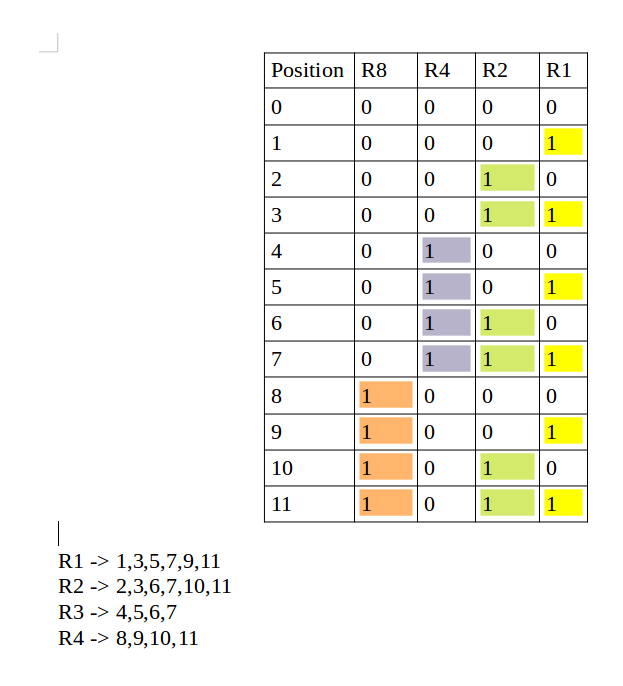
- Parity bit 1 (R1): Checks positions whose binary representation has 1 in the least significant bit: 1, 3, 5, 7, 9, 11, ...
- Parity bit 2 (R2): Checks positions whose binary representation has 1 in the second bit from the right: 2, 3, 6, 7, 10, 11, ...
- Parity bit 4 (R4): Checks positions whose binary representation has 1 in the third bit from the right: 4–7, 12–15, 20–23, ...
- Parity bit 8 (R8): Checks positions whose binary representation has 1 in the fourth bit from the right: 8–15, 24–31, 40–47, ...
In general, a parity bit checks every position whose binary representation has 1 in the corresponding bit position.
Step 5: Calculate each parity bit using the selected parity rule. For even parity, set the parity bit so that the total number of 1s in its checked positions is even.
Step 6: During reception, the parity bits are checked again. The results form a binary value indicating the position of the erroneous bit, which can then be corrected by flipping that bit. If the binary value is 0, there is no error.
 Determining The Position of Redundant Bits
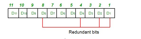
The redundant bits are placed at positions that correspond to the power of 2. As in the above example:
- The number of data bits = 7
- The number of redundant bits = 4
- The total number of bits = 7+4=11
- The redundant bits are placed at positions corresponding to power of 2 that is 1, 2, 4, and 8
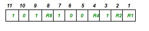
- Suppose the data to be transmitted is 1011001 from sender to receiver, the bits will be placed as follows:
Determining The Parity Bits According to Even Parity
- R1 bit is calculated using parity check at all the bits positions whose binary representation includes a 1 in the least significant position. R1: bits 1, 3, 5, 7, 9, 11
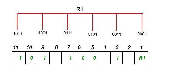
- To find the redundant bit R1, we check for even parity. Since the total number of 1’s in all the bit positions corresponding to R1 is an even number. So, the value of R1 (parity bit’s value) = 0.
- R2 bit is calculated using parity check at all the bits positions whose binary representation includes a 1 in the second position from the least significant bit. R2: bits 2, 3, 6, 7, 10, 11
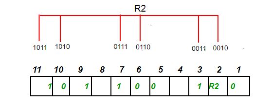
- To find the redundant bit R2, we check for even parity. Since the total number of 1’s in all the bit positions corresponding to R2 is odd the value of R2(parity bit’s value)=1
- R4 bit is calculated using parity check at all the bits positions whose binary representation includes a 1 in the third position from the least significant bit. R4: bits 4, 5, 6, 7
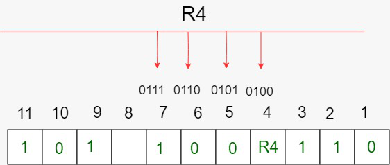
- To find the redundant bit R4, we check for even parity. Since the total number of 1’s in all the bit positions corresponding to R4 is odd so the value of R4(parity bit’s value) = 1
- R8 bit is calculated using parity check at all the bits positions whose binary representation includes a 1 in the fourth position from the least significant bit. R8: bits 8, 9, 10, 11
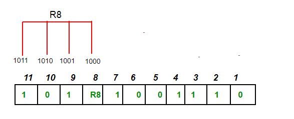
- To find the redundant bit R8, we check for even parity. Since the total number of 1’s in all the bit positions corresponding to R8 is an even number the value of R8(parity bit’s value)=0. Thus, the data transferred is:

Error Detection and Correction
Suppose in the above example the 6th bit is changed from 0 to 1 during data transmission, then it gives new parity values in the binary number:
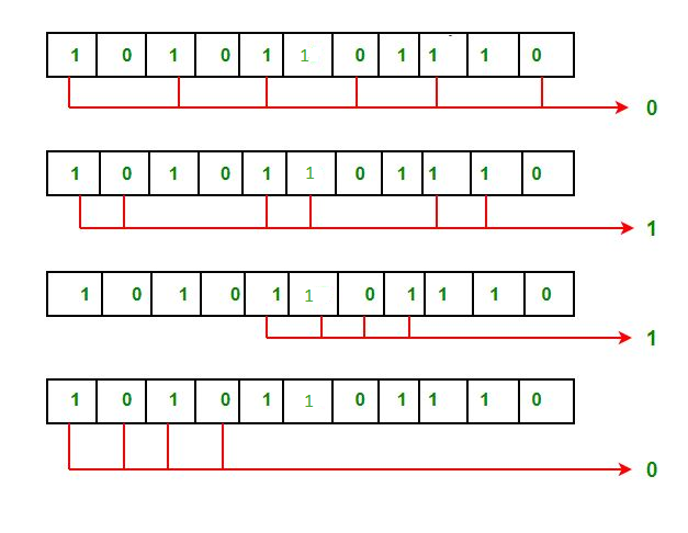
For all the parity bits we will check the number of 1's in their respective bit positions.
- For R1: bits 1, 3, 5, 7, 9, 11. We can see that the number of 1's in these bit positions are 4 and that's even so we get a 0 for this.
- For R2: bits 2, 3, 6, 7, 10, 11 . We can see that the number of 1's in these bit positions are 5 and that's odd so we get a 1 for this.
- For R4: bits 4, 5, 6, 7 . We can see that the number of 1's in these bit positions are 3 and that's odd so we get a 1 for this.
- For R8: bit 8, 9, 10, 11 . We can see that the number of 1's in these bit positions are 2 and that's even so we get a 0 for this.
- The bits give the binary number 0110 whose decimal representation is 6. Thus, bit 6 contains an error. To correct the error the 6th bit is changed from 1 to 0.
Features
- Error Detection and Correction: Hamming code is designed to detect and correct single-bit errors that may occur during the transmission of data. This ensures that the recipient receives the same data that was transmitted by the sender.
- Redundancy: Hamming code uses redundant bits to add additional information to the data being transmitted. This redundancy allows the recipient to detect and correct errors that may have occurred during transmission.
- Efficiency: Hamming code is a relatively simple and efficient error-correction technique that does not require a lot of computational resources. This makes it ideal for use in low-power and low-bandwidth communication networks.
- Widely Used: Hamming code is a widely used error-correction technique and is used in a variety of applications, including telecommunications, computer networks, and data storage systems.
- Single Error Correction: The basic Hamming code can correct only one bit error per data unit; if two bits flip at once, it will miscorrect rather than detect the problem correctly.
- Limited Multiple Error Detection: Hamming code cannot correct multi-bit errors and may miscorrect them as a single-bit error instead. Adding an extra parity bit lets it detect (but not correct) two-bit errors.
